
Email us
![]()
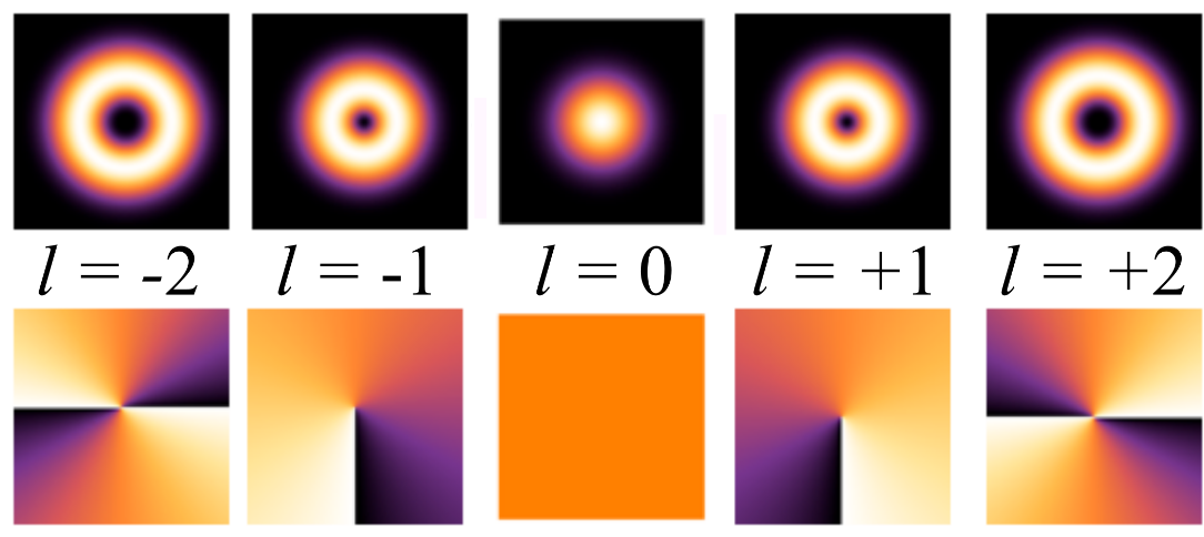
Intensity distributions (top row) and phase of the wave-fronts (bottom row) for different OAM modes, . This figure has been adapted from [2].
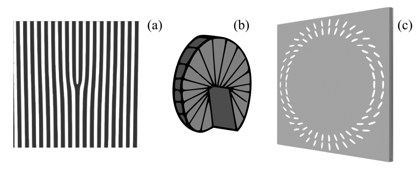
Schematic diagrams of (a) a holographic l-fold forked diffraction grating[4], (b) a spiral phase plate[5], and (c) an OAM tailored metamaterial[6].
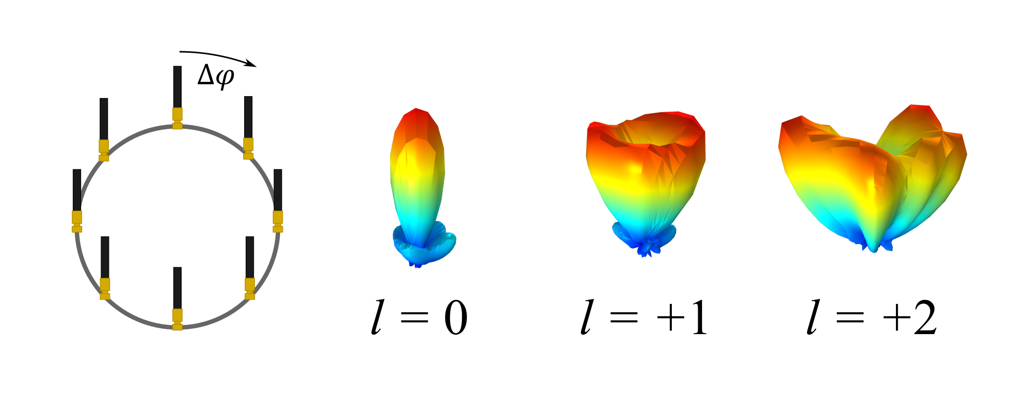
Schematic diagram of an 8-element uniform circular array of antennas (UCA). Example far-field radiation patterns (simulated by using COMSOL Multiphysics®) are also shown for and to visualise the divergence of the beam for increasing OAM mode number.

Radio Orbital Angular Momentum: Here to Revolutionise Wireless Communications?
Author: Dr Joshua Hamilton
The research behind this piece was supported by TEAM-A's Research Challenge 1.
One of the investigations being undertaken by TEAM-A is to demonstrate the practical uses of radio frequency orbital angular momentum (OAM) beams. Radio frequency OAM could be used to improve the spectral efficiency of communication by multiplexing parallel data streams along multiple OAM modes at the same frequency. Other possible applications exist in radio astronomy research - for example: exoplanet detection, radar probing of the Sun, and in the detection of ultrahigh energy neutrinos.
It is well known that electromagnetic waves carry both momentum and energy. The carried momentum comprises linear momentum P and angular momentum L. In general, the angular momentum comprises of two components, which are associated with different phenomena of the electromagnetic wave: the spin angular momentum is an additive component linked to polarization (spin angular momentum - SAM), and the orbital angular momentum is associated with the spatial distribution (orbital angular momentum - OAM). To help understand these phenomena by analogy, take the Earth orbiting the Sun. The orbital motion of the Earth around the Sun (resulting in the yearly circle) is equivalent to OAM; whereas SAM would be equivalent to the Earth spinning on its axis (resulting in the day/night cycle).
OAM modes first came to optical physicists’ attention in 1992, where the idea of an optical vortex was linked to OAM[1]. In an optical vortex the planes of constant phase of the electric and magnetic vector field form a corkscrew in the direction of propagation. This helical structure is characterised by the number of twists the light does within one wavelength. Due to the helical structure of the wave-front, there is a null in the axial centre of the beam – for all modes other than (the plane wave mode). Examples of the magnitude and phase of the OAM modes, are shown in Figure 1. The null in the centre of the beam has been shown to be useful for trapping cells in so-called optical tweezers/spanners. Theoretically speaking, the OAM carried by the optical vortex has an infinite number of eigenstates, resulting in the enormous interest in the past 15 years.
The idea of using helical waves to carry OAM is not only restricted to the optical. In the past decade there has been a vast amount of interest in translating the basic physical concept to radio frequencies, due to the promise of ground-breaking enhancements in wireless communications. Since the first simulations of radio OAM[3] were shown in 2007, the radio communications community have proposed multiple methods of generating helical radio beams. Such methods include: holographic l-fold forked diffraction gratings[4]; spiral phase plates[5] (imagine a rotating step so that the thickness increases with azimuth angle); metamaterials[6] (structures comprising sub-wavelength units that can manipulate the phase, amplitude, and polarization of the wave-front); and uniform circular arrays (circular arrays of antennas, separated by a given phase). Schematics of the typical methods of generating radio frequency OAM beam are shown in Figure 2. For more information regarding methods of generating radio frequency OAM beams, please see a recent review article of the field[7].
TEAM-A are interested in utilising the uniform circular antenna array (UCA) method. The typical UCA is comprised of N elements, uniformly distributed on the circumference of a circle[8]. Each element is given the same amplitude; however, the phase difference between to neighbouring elements is given by , where l is the OAM mode number, and N is the number of elements. The helical waves generated by UCAs are typically distortion-free up to |. Figure 3 shows a schematic of an 8-element UCA system and the modelled (COMSOL Multiphysics®) examples of the far-field radiation pattern (see equation 1).
The crucial drawback of OAM carrying beam being used for applications is the central vortex. For increasing OAM modes, the divergence angle of the beam increases (see Figure 1). As a result, the receive aperture size required for optimum reception scales with the OAM mode (which is undesirable). One method of transmitting and receiving an OAM beam is to only receive a partial component of the beam. The issue with this method is that the receiving of a partial component would result in a loss of power and transmitted information. The main aim of the TEAM-A work is to investigate methods of controlling the divergence of the beam without affecting the OAM structure of the beam. To could allow for a more feasible design for the long-range transmitter/receiver systems that are required for real-world applications.
References
[1] L. Allen, M. W. Beijersbergen, R. J. C. Spreeuw, and J. P. Woerdman, “Orbital angular momentum of light and the transformation of Laguerre-Gaussian laser modes,” Phys. Rev. A, vol. 45, no. 11, pp. 8185–8189, 1992.
[2] Wikipedia, “Orbital angular momentum of light” 2019. [Online]. Available: https://en.wikipedia.org/wiki/Orbital_angular_momentum_of_light. [Accessed:02-May-2019].
[3] B. Thidé, H. Then, J. Sjöholm, K. Palmer, J. Bergman, T. D. Carozzi, Ya. N. Istomin, N. H. Ibragimov, and R. Khamitova, “Utilization of photon orbital angular momentum in the low-frequency radio domain,” Phys. Rev. Lett., vol. 99, no. 8, pp. 1–4, 2007.
[4] F. E. Mahmouli and S. Walker, “4-Gbps Uncompressed Video Transmission over a 60-GHz Orbital Angular Momentum Wireless Channel,” IEEE Wireless Communications Letters, vol. 2, no. 2, pp. 223-226, 2013.
[5] L. Zhu, X. Wei, J. Wang, Z. Zhang, Z. Li, H. Zhang, S. Li, K. Wang, and J. Liu, “Experimental demonstration of basic functionalities for 0.1-thz orbital angular momentum (OAM) communications,” Optical Fiber Communication Conference 2014, pp. 1–3, 2014.
[6] Zhe Zhao, Jian Wang, Shuhui Li, and Alan E. Willner, "Metamaterials-based broadband generation of orbital angular momentum carrying vector beams," Opt. Lett. vol. 38, pp. 932-934, 2013.
[7] A. E. Willner, Y. Ren, G. Xie, Y. Yan, L. Li, Z. Zhao, J. Wang, M. Tur A. F. Molisch, and S. Ashrafi “Recent advances in high-capacity free-space optical and radio-frequency communications using orbital angular momentum multiplexing,” Philosophical Transactions of the Royal Society A: Mathematical, Physical and Engineering Sciences, vol. 375, no. 2087, pp. 20150439, 2017.
[8] T. D. Drysdale, B. Allen, C. Stevens, S. J. Berry, F. C. Smith, and J. Coon, “How orbital angular momentum modes are boosting the performance of radio links,” IET Microwaves, Antennas Propag., vol. 12, no. 10, pp. 1625–1632, 2018.