Email us


A graph of the calculated IR against time/s. The point at which this was windowed to give the modified impulse response MR is shown.

A graph of the voltage of the synthesised signal (blue) and recorded signal (pink) against timefor 10kHz sine input signal showing the time difference.

a) Upper left: 2kHz sine input
c) Lower left: 2kHz sine input with reflections removed in synthesised signal

b) Upper right: 15kHz sine input
d) Lower right: 15kHz sine input with reflections removed in synthesised signal
Measuring Low Frequency Acoustic Signals in a Restricted Volume of Water
Author: Madeline Stedman (University of Exeter Undergraduate of Natural Sciences)
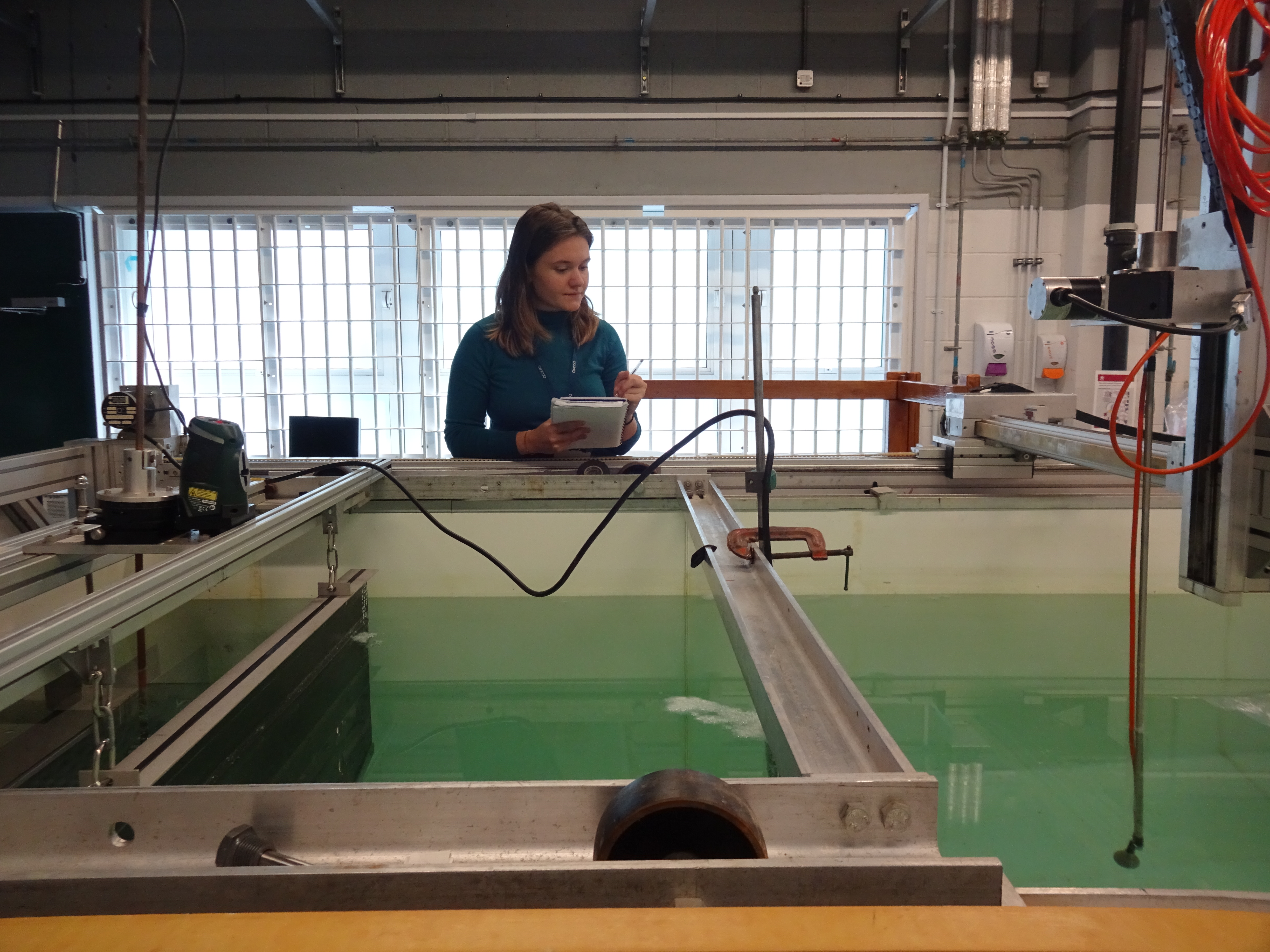
During my summer internship at QinetiQ as part of University of Exeter’s TEAM-A research programme I conducted the following experiment to measure low frequency acoustic signals in water. Acoustic properties of water can be investigated using two hydrophones, one as a transmitter and one as a receiver, by measuring the distortion of an acoustic signal between them. Once the effects of water are known, the underwater acoustic properties of materials can then be investigated by placing them in between the hydrophones.
Ideally these experiments would be carried out in open water so the only signal received is that coming along the most direct path from the transmitter with no reflected signals complicating the distortion. However for laboratory based experiments this is impractical and expensive so the volume of water is restricted. This sets a limit on the minimum frequency of signal that can be used, as below this limit the reflected signals overlap and interact with the signal arriving along the direct path. The aim of this work was therefore to find a way to take low frequency measurements in a tank of water of dimensions approximately 1.2m by 2m by 1.2m. In order to do this I designed and carried out experiments aiming to obtain a proof of concept for a method provided by Graham Alker of SMTA ltd. that removes reflections from the received signal by modifying the transfer function, a mathematical function relating the received and input signals.
Graham Alker’s transfer function method is described as follows:
- Record input signal (to be transmitted by hydrophone) for a chirp (f). The chirp signal used was initially a linear frequency modulation but this was later changed to a power weighted frequency modulation which accounted for the frequency dependent sensitivity of the transmitting hydrophone which resonated at about 80kHz.
- Record signal received (g) from this input
- Transfer function = H=(fft(g))/(fft(f))
- Record input of five cycles of a sine wave at any frequency within the chirp frequency range (a)
- Synthesise the received signal for this input = r=ifft(fft(a)×H)
The first stage of the experiment was to achieve a proof of concept for this method without removing reflections by comparing the synthesised received signal to the recorded received signal. The minimum frequency limit for measurements in this tank was found to be roughly 15kHz so a chirp frequency range of 1kHz to 30kHz was used and the received signals were both recorded and synthesised for sine wave inputs at frequencies 0.5, 1, 2, 4, 6, 8, 10, 15kHz. Frequencies outside the chirp frequency range were used to consolidate the proof of concept as the transfer function should contain no information at these frequencies so the sythesised and recorded received signals should not align. For each signal recording, 256 measurements were taken and time averaged to improve the signal to noise ratio. The tank was found to return to the noise floor 0.1s after a signal so a delay of 0.5s between measurements was used.
Once this was shown to be successful, the second stage of the experiment involved modifying the transfer function to remove reflections from the synthesised received signal. The impulse response (IR) was found by taking the ifft of the transfer function. The IR shown in figure 1 consisted of a large peak corresponding to the direct signal arriving at the hydrophone followed by several smaller peaks corresponding to reflections from each of the surfaces within the tank. By windowing the IR to be zero for all time values after the first peak, as shown in figure 1, the modified impulse response (MR) was obtained. This was used to define the modified transfer function (MH) as the fast Fourier transform of the MR. The MH represented the transfer function that would have been obtained had the experiment been performed in open water. Steps four and five from stage one were then repeated replacing H with MH to synthesise the signals that the hydrophone would have received in open water.
Upon initial comparison of the synthesised and recorded received signals for stage one of the experiment a problem was encountered. A time difference of 20ms was observed between the synthesised and recorded signal as shown in figure 2. This was constant for all frequencies suggesting it was a systematic error caused by the LabVIEW software/apparatus rather than due to experimental error. After further investigation it was found that when LabVIEW generates the waveform from a list of values in a .txt file rather than from a formula it creates a time delay. A solution was therefore to generate all input signals for the chirp and sine waves using values in .txt files or all from formulas.
After correcting this error the proof of concept was found to be successful as the synthesised signals accurately matched the recorded signals for five sine waves at frequencies 2,4,6,8,10,15kHz as shown in figure 3a,b. The synthesised signals were significantly different to those recorded for frequencies 0.5 and 1kHz as expected, confirming that the frequencies used must be within the range of the chirp. Following on from this proof of concept, the modified transfer function was determined and used successfully to synthesise received signals with all reflections ‘deleted’ as can be seen in figure 3c,d. The direct and reflected components of the recorded 15kHz signal could be easily separated by eye so this was used to verify the success of the synthesised signal with reflections removed.
To further improve the results for this method the effect of changing the number of cycles of sine waves, length of chirp input signal and amplitude of input signals could be investigated.
Surface (and other boundary) reflections in small experimental water tanks limit their use to frequencies above a certain value. For the tank at QinetiQ this limit is 15kHz. It has been demonstatred that the tank can be used down to 2kHz. Further experiments and analysis may show that this limit may be lowered.

